Bend Rad For 16g Sheet Metal

How To Choose Cut And Bend Sheet Metal Make

Home Made Sheet Metal Brake Sheet Metal Brake Metal Bending Tools Metal Working Tools

Homemade Sheet Metal Bender Sheet Metal Bender Metal Bender Sheet Metal Brake

Eastwood Metal Cutting Tools How To Cut Sheet Metal To Thick Plate Youtube

How To Bend Sheet Metal 13 Steps With Pictures Wikihow

10 6 Aluminum Steel Metal Trim Siding Brake 26g Steel Stand Slitter Included Ebay Siding Trim Sheet Metal Fabrication Metal Trim

To help this blog will explain the gauge system and features a sheet metal gauge chart.
Bend rad for 16g sheet metal.

Sheetmetal Stakes By Andersk Homemade Sheetmetal Stakes Forged From Steel And Surplus Suspension Coil Sheet Metal Fabrication Metal Fabrication Sheet Metal

How To Make A Sheet Metal Box Sheet Metal Sheet Metal Fabrication Metal Box

48 Press Brake Project Page 6 Pirate4x4 Com Metal Working Tools Press Brake Welded Metal Projects

Ultimate 48 16ga Box Pan Brake With Radius Fingers By Mittler Bros Metal Fabrication Tools Sheet Metal Brake Sheet Metal Fabrication

Pin By Todd Landon On 718 Metal Shaping Sheet Metal Work Metal Working

Diy Sheet Metal Brake Pirate4x4 Com 4x4 And Off Road Forum Sheet Metal Brake Metal Working Tools Metal Workshop

Metal Brake Sheet Bender Sheet Metal Fabrication Sheet Metal Brake Metal Bending Tools

Image Result For Pullmax Radius Dies Sheet Metal Fabrication Custom Metal Fabrication Sheet Metal Tools
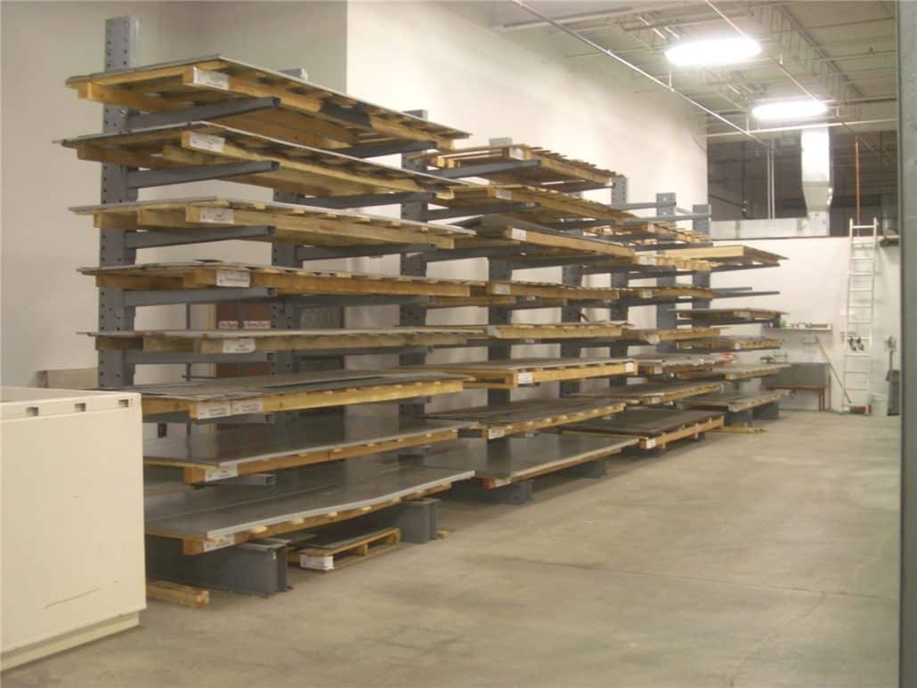
Steel Sheet Metal Flat Stock Sheets Denver Colorado H H Metals

Home Made Sheet Metal Brake Pirate4x4 Com 4x4 And Off Road Forum Sheet Metal Brake Sheet Metal Bender Metal Bending Tools

Miller Welding Projects Idea Gallery Tubing Bender Welding Projects Metal Working Projects Metal Working

Homemade Bending Tool Sheet Metal Brake Youtube Sheet Metal Brake Sheet Metal Bender Sheet Metal

Simple Sheet Metal Brake No Welding Sheet Metal Sheet Metal Brake Sheet Metal Bender

Diy Sheet Metal Repair Patching Youtube Welding Projects Welding Welding Jobs

36 In Metal Brake With Stand

Sheet Metal Hole Punch And Dimple Die Imgur Hole Punch Sheet Metal Metal Shaping

Sheet Metal Notchers For Race Car Fabrication Metal Working Tools Metal Metal Shaping

Crater Maker 3 8 4140 Hardened Dimple Dies Sheet Metal Fabrication Sheet Metal Tools Metal Tools
Https Encrypted Tbn0 Gstatic Com Images Q Tbn 3aand9gcqixqh95xphsspyaxiuwtw11ktvln5thwpqlxg83vqt2ywsiwnz Usqp Cau

Sheet Metal Bender Brake The Make Diy First Use Stainless Steel Bbq Youtube Metal Shop Metal Bender Metal Working Tools
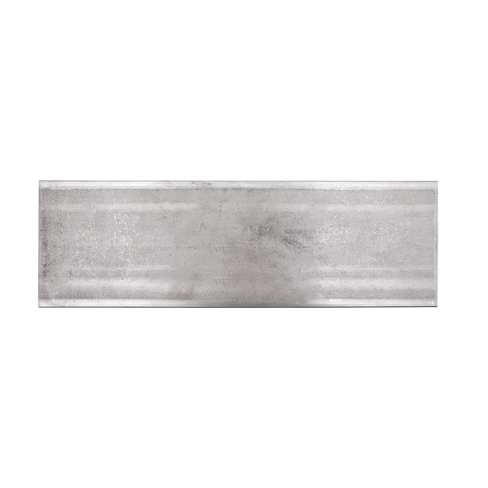
Steel Sheet Metal Metal Stock The Home Depot
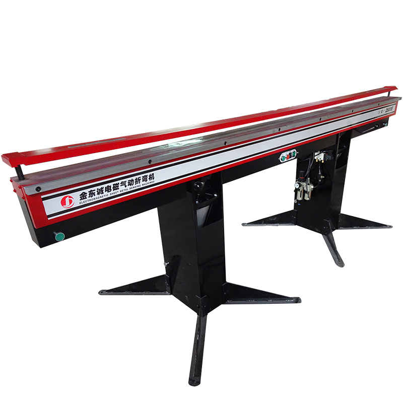
China Cheap Price Sheet Metal Bending Machine 2mm 2500e Powered 2500mm X 1 6mm Electromagnetic Sheet Metal Folding Machine Jindongcheng Manufacturer And Supplier Jindongcheng

Amazon Com Eastwood Sheet Metal Fabrication Bead Roller Kit Forming Mandrels Automotive Sheet Metal Fabrication Metal Bending Tools Metal Working Tools

1969 Camaro Custom Hood Vent Fabrication Custom Metal Fabrication Sheet Metal Fabrication Metal Fabrication
Source : pinterest.com
